
Survey Point Dataset Cleaning and TIN Surface Modeling
Learn standard procedures for extracting Civil 3D alignment exports, validating vertical curve K-values, calculating superelevation runoff transitions, and processing DTM survey datasets.
ℹ️ Instructional Notice:
All station chainages and coordinate references demonstrated in these workflows use synthetic example data created solely for technical instruction and software verification.
Tutorial Courses (4)
Survey Point Dataset Cleaning and TIN Surface Modeling
A comprehensive guide to filtering total station survey points, cleaning description codes, enforcing 3D breaklines, and checking Digital Terrain Models (TIN surfaces) in Civil 3D.
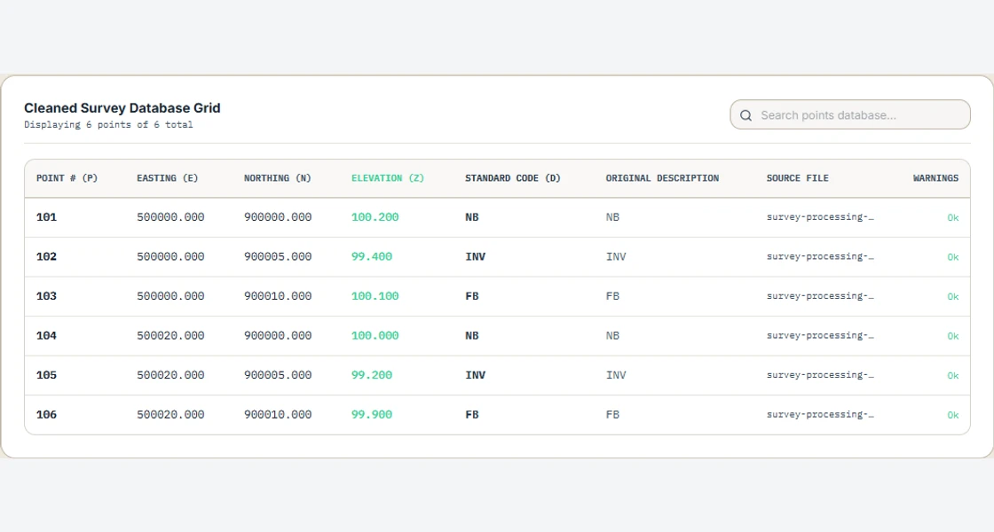
Step 1: Check Raw Coordinate Formats (PENZD vs PNEZD)
Verify raw field survey text files from data collectors before importing. Ensure columns follow either PENZD (Point, Easting, Northing, Elevation, Description) or PNEZD (Point, Northing, Easting, Elevation, Description).
Check UTM coordinates: in UTM Zone 37N, Easting is a 6-digit number (~450,000 to ~550,000m) while Northing is a 7-digit number (~900,000 to ~1,100,000m). Swapping eastings and northings displaces and reflects the dataset about the E = N line. Check the coordinate order against a known point and the project coordinate system.
Step 2: Clean Duplicates and Filter Elevation Spikes
Upload the raw CSV to Infradigital's Survey CSV Cleaner. The automated filter scans for:
- Duplicate Point IDs: Multiple points sharing Point ID 101 are automatically renumbered sequentially.
- Zero Elevation Spikes: GPS lost-lock points with Z = 0.00m or 9999.00m are isolated and purged to prevent massive sinkhole spikes in the DTM.
- Description Standardization: Strips leading/trailing spaces and harmonizes codes (e.g., converting " cl " to "CL").
Step 3: Standardize Feature Codes for Automated Linework
Ensure feature codes include Civil 3D Linework Code Set command suffixes:
| Feature Code | Suffix Command | Civil 3D Action |
|---|---|---|
| CL B | B | Begins a new Centerline 3D breakline |
| EP_L PC | PC | Begins a circular curve on Edge of Pavement |
| EP_L PT | PT | Ends tangent curve on Edge of Pavement |
| TOE_L E | E | Ends Toe of Slope breakline |
Step 4: Enforce 3D Structural Breaklines in Civil 3D
Save the cleaned PENZD file. In Civil 3D Toolspace > Prospector, right-click Surfaces > Create Surface. Name it EG_Surface.
Expand EG_Surface > Definition. Right-click Point Files and add your cleaned CSV. Next, right-click Breaklines and select Add. Add your 3D survey figures as Standard Breaklines with Mid-Ordinate Distance = 0.10m.
Enforcing breaklines guarantees that triangulation edges snap to physical features (curbs, ditches, ridges) rather than spanning across channels.
Step 5: Audit Surface Triangulation & Eliminate Flat Areas
In Surface Properties > Definition Tab > Build options, set Minimize Flat Areas to Yes. Enable edge swapping and point addition.
Switch the Surface Style to Contour & Triangles. Visually inspect the TIN: verify that no long, skinny sliver triangles extend beyond the survey perimeter, and ensure that stream flowlines follow true surveyed invert elevations.
Step 6: Export Clean Surface & Perform Volumetric Checks
Once audited, your Digital Terrain Model is ready for corridor modeling. Use the Water Drop tool to verify that drainage traces accurately follow ditch channels without becoming trapped in phantom depression sinks.